Mechanics
Scale
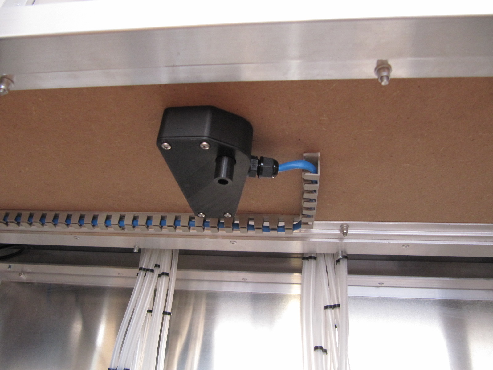
To measure the poured quantities of the ingredients, a load cell in conjunction with a HX711 is used. Before assembling the printed plastic parts, the overflow pipe must be glued into the scale pan. The balance is bolted on from above through the table top. The length of the spacer and the overflow pipe must be adjusted according to the thickness of the table top, a gap of about 1 mm should be visible between the table top and the scale pan. For the electrical connection we used a CAT5e cable. On the bottom of the housing, it is possible to connect a hose with 10 mm inner diameter for the overflow. The following sequence has proven useful for the assembly of the scale:
-
Screw the cable gland into the housing,
-
Position housing and load cell under the table top,
-
Screw the load cell from the top,
-
Secure spacers and scale pan,
-
Solder cables,
-
Screw on the lid.
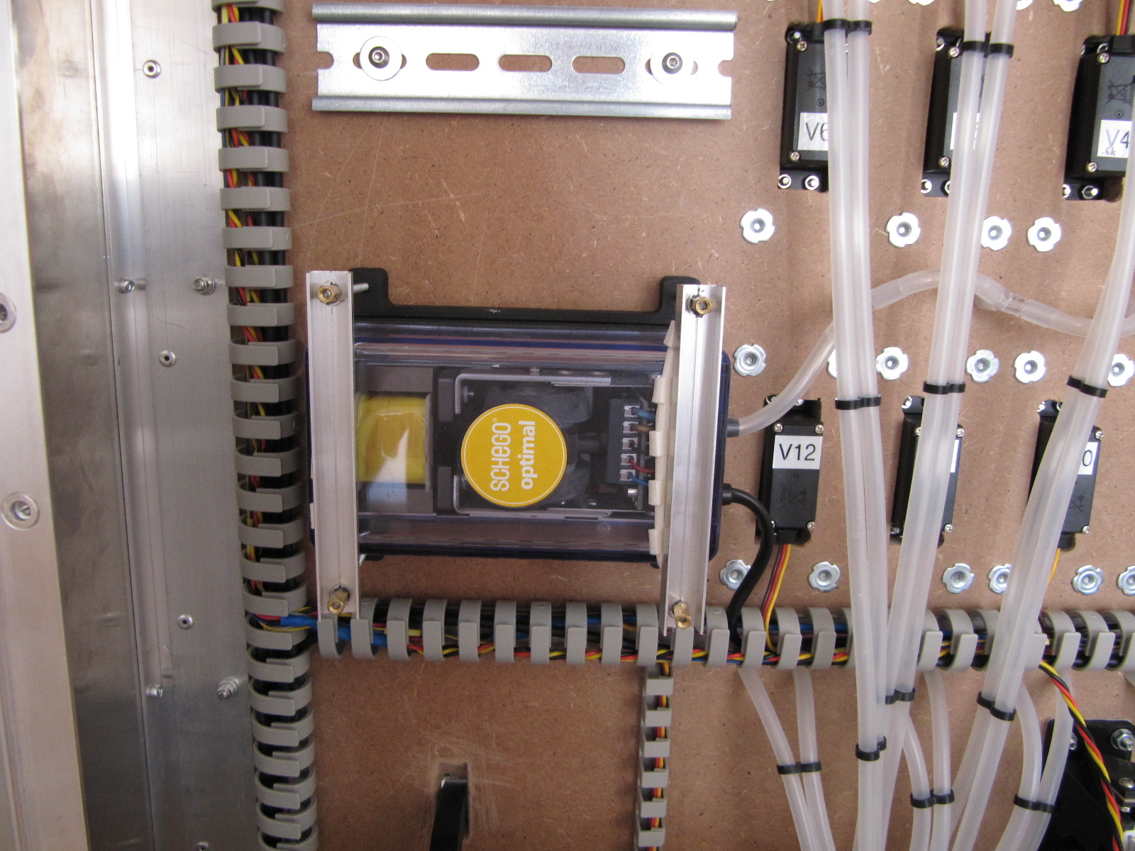
Pump
To create the overpressure in the bottles, we use an air pump for fish tanks. Since the complete electronics operate with max. 12 VDC, we opted for a 12 V pump from Schego. The selection of the pump is relatively uncritical since the required pressure and the flow rate are low. It should only be ensured that the pump works oil-free. Because the pump has only one hole for mounting, a bracket has been designed. The following sequence during assembly has proven itself:
-
Screw on 2 nuts at each end of the threaded rods and counter. A nut should be flush with the threaded rod, the key surfaces of the nuts must be in alignment.
-
Insert threaded rods in the holes of the bracket,
-
Screw the bracket into the housing,
-
Insert pump and clamp with the U-profiles (optionally with foam rubber strips under the U-profiles),
-
Counter the nuts (or glue with Loctite).
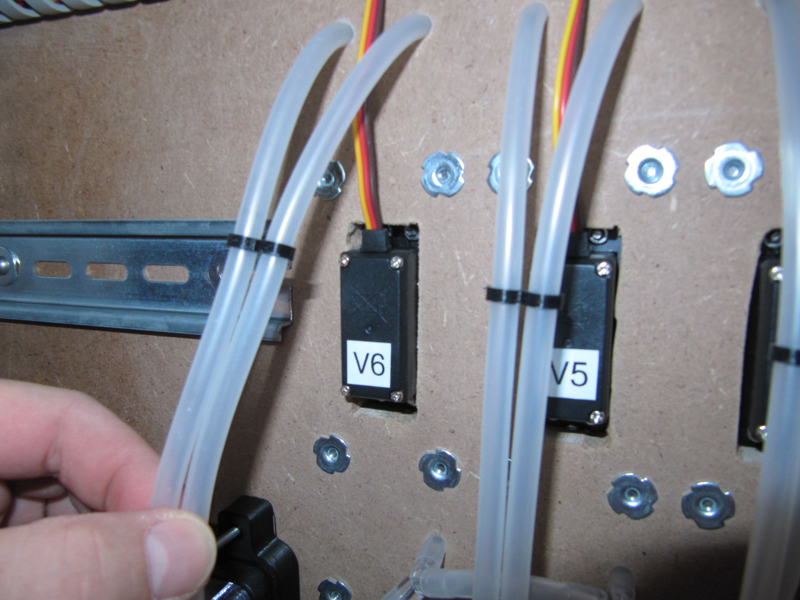
Valves
In order to realize the dosing of the fluids, pinch valves were designed
for our cocktail machine which simultaneously open and close both hoses
(i. e. air and liquid) for an ingredient.
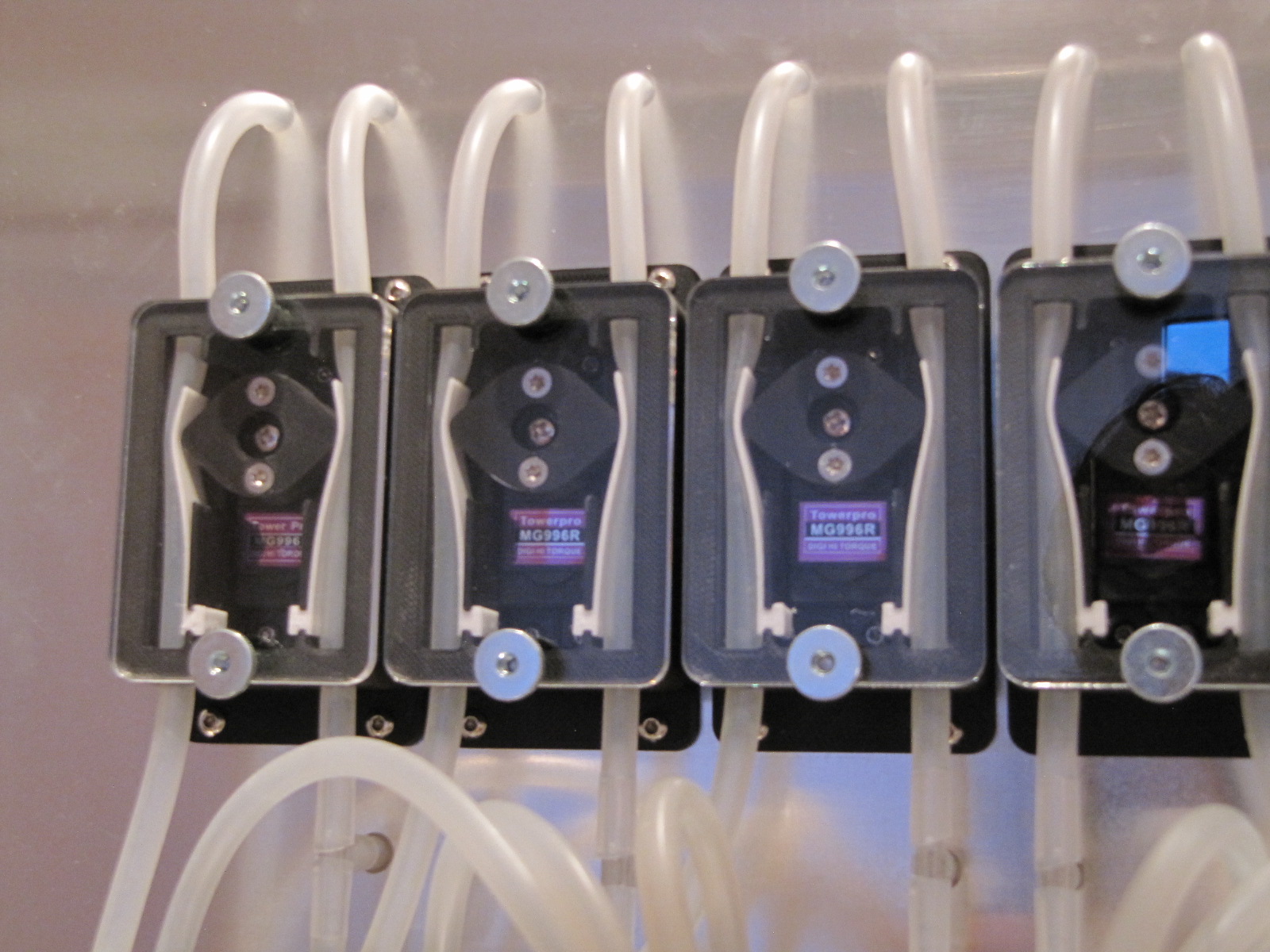
The required plastic parts for the valves can be printed without
support. The (optional) cover was cut out of transparent PMMA with a
CO~2~ laser. Make sure the servos are original TowerPro MG996R. There
are servos with the same name of no-name vendors. These servos may
differ in the outer dimensions, in some cases significantly different
from the original servos. The round servo arms supplied with the servos
must be adapted to the inner diameter of the cams. Special care is
necessary: If the servo arms are eccentric in the cam, the valve will
not close properly. Our servo arms were machined on a CNC milling
machine with a very sharp wood cutter. The mounting holes for the servo
arms are best drilled using the cam as a template. The screws for
connecting cam and servo arm are secured with Loctite. Make sure the
tongues are made of a material with good sliding properties. Our tongues
were printed from Iglidur I150. The tongues in the valves of Uncle
Hector have been through a few hundred cycles and still work flawlessly.
Alternatively, the tongues could be printed from PET, but this has not
been tested yet. For the valves to sit flush with the rear wall, cutouts
for the servos must be made (Fig. 4).
For fastening the valves, captive nuts have
been proven.
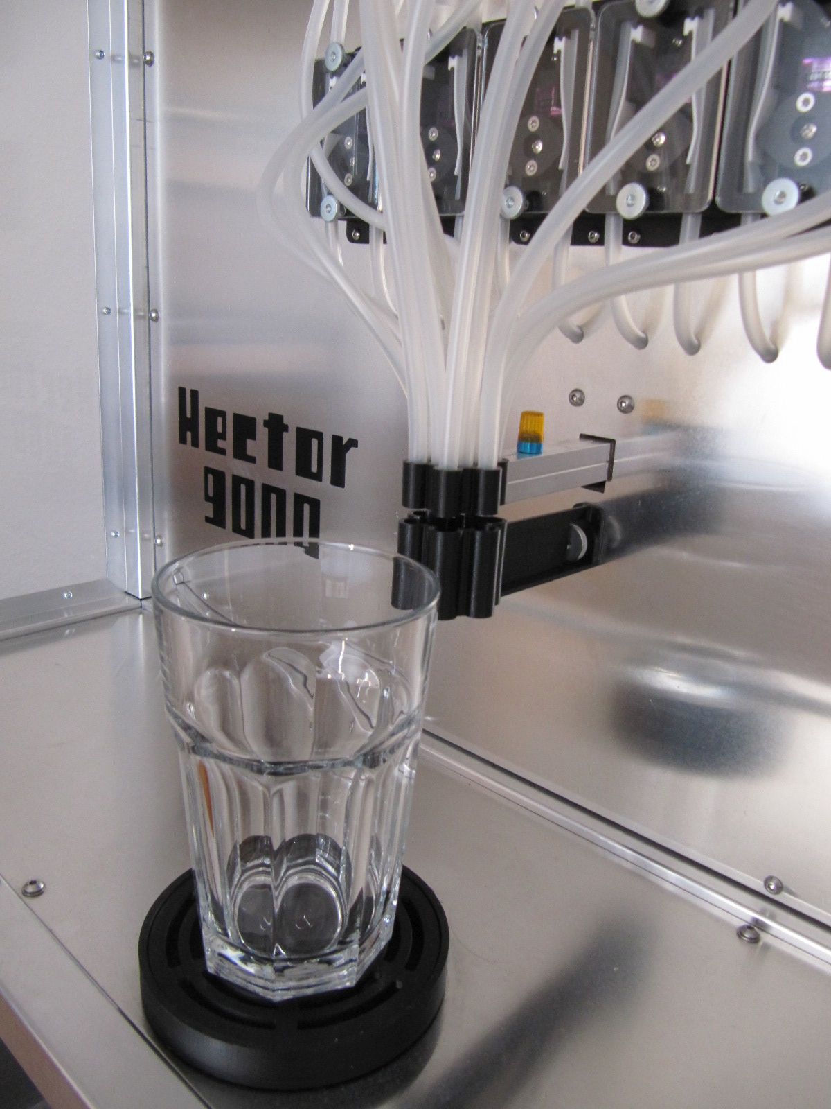
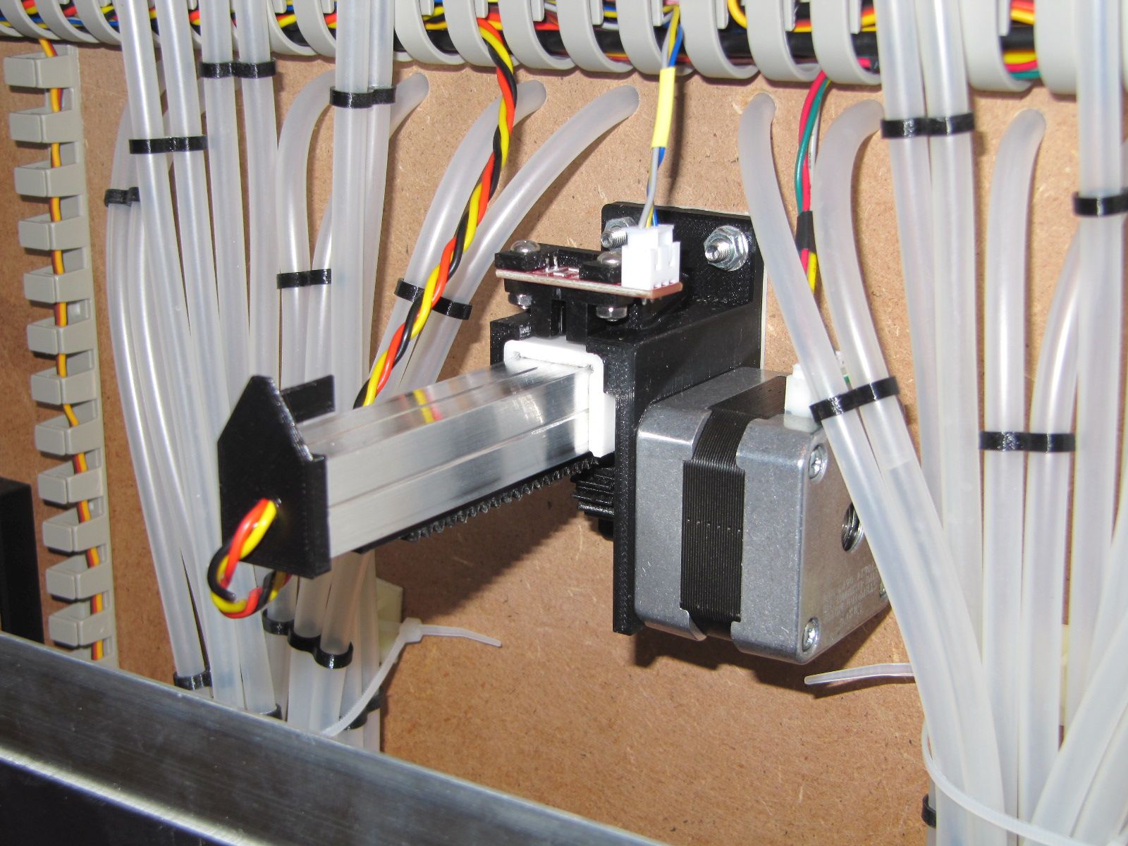
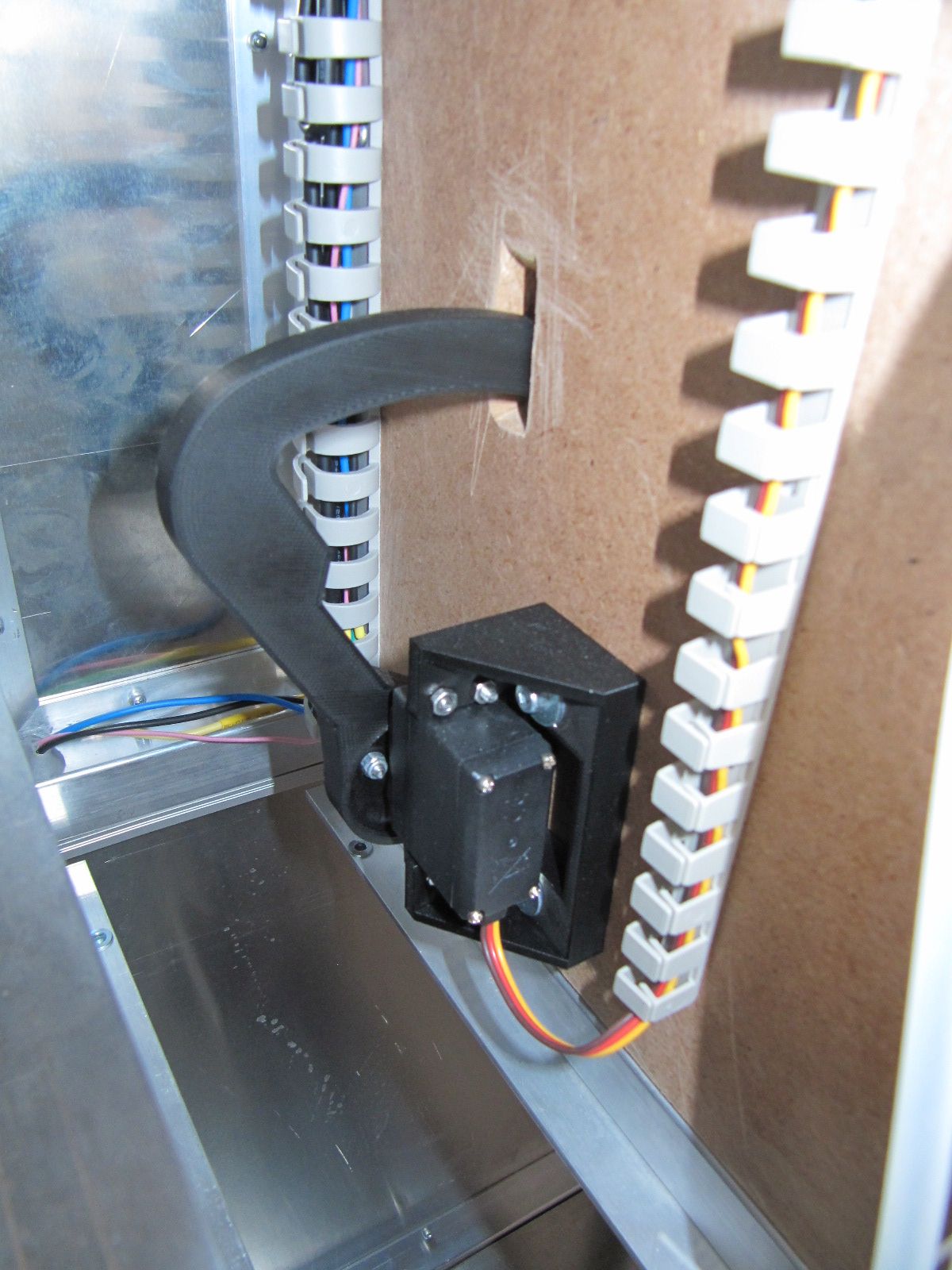
Arm
In order to make the filling process more comfortable, the arm with the
dosing head is retracted in the idle state
(Fig. [arm_front_in]). When the dosing process is started, the arm
moves forward. All required plastic parts can be printed without
support. The gliding insert should be made of a material with good
sliding properties. Our gliding insert was printed from Iglidur I150.
Alternatively, the slide insert could be printed from PET, but this has
not been tested yet. The boom consists of an aluminum profile with
15.5 mm edge length. Such profiles can be found in almost every German
DIY store. The pinion is pressed onto the shaft of the motor and needs
no further securing. To attach the rack to the boom, M3 blind rivet nuts
were inserted into the profile. The dosing head is secured with a
self-tapping screw in the profile. The trigger is glued to the boom. The
trigger has a hole through which a cable was routed to power an optional
all-round light on the arm.
When mounting the arm, make sure that the bottom bolt is passed through
the hole from the rear and screwed down with a regular nut. The upper
bolts are inserted from the front through the rear wall. The drip
catcher can now be mounted on the lower screw with a knurled nut
(Fig. [drip]).
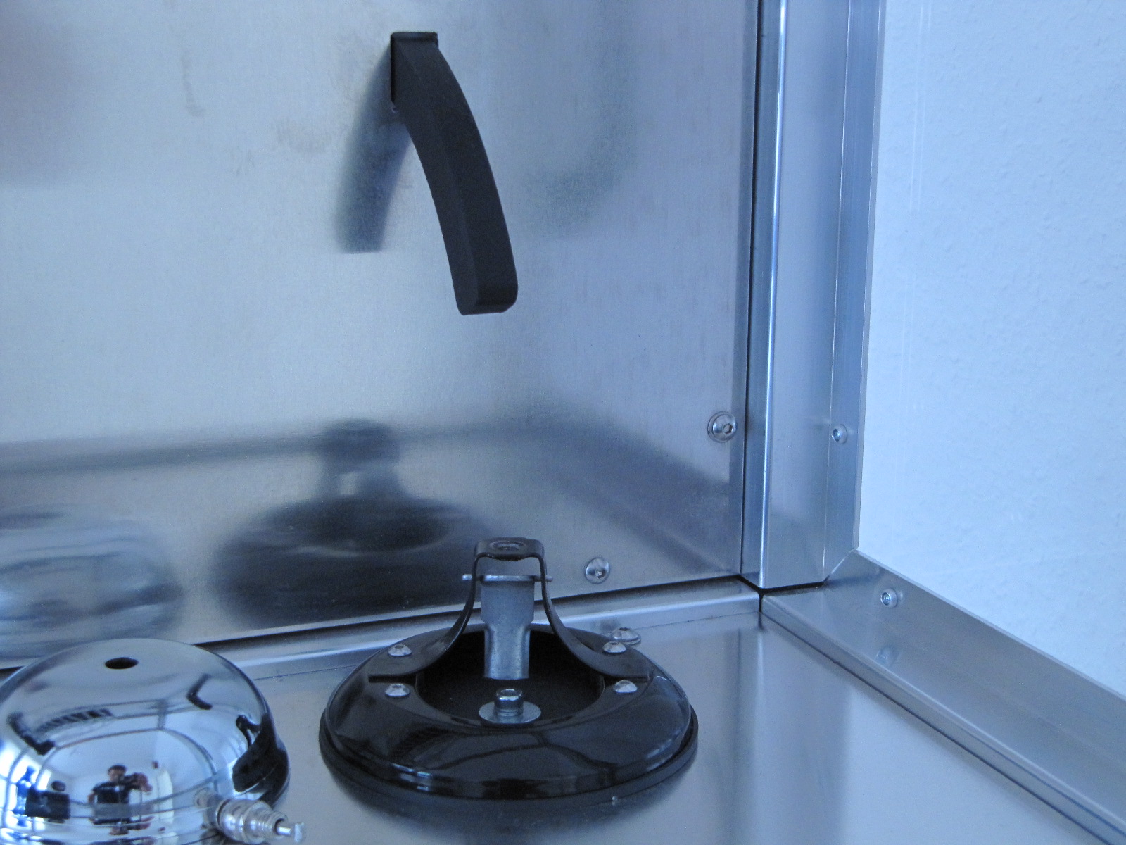
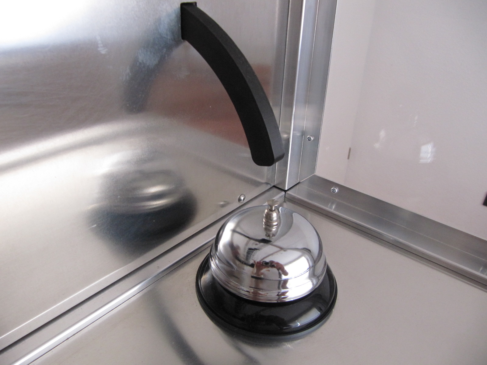
Bell
When building the mechanism for the bell, make sure that the center of the bell is 100 mm away from the rotational axis of the arm. A bracket is provided for attaching the bell (Fig. 6). To drill the necessary holes in the bell, the bracket is used as a drilling jig. The mounting of the finger on the back wall is actually self-explanatory. To attach the motor bracket (Bell_servo-bracket.stl) to the rear panel, it is advisable to use captive nuts or threaded inserts, so the finger can be easily adjusted later (Fig. 8).
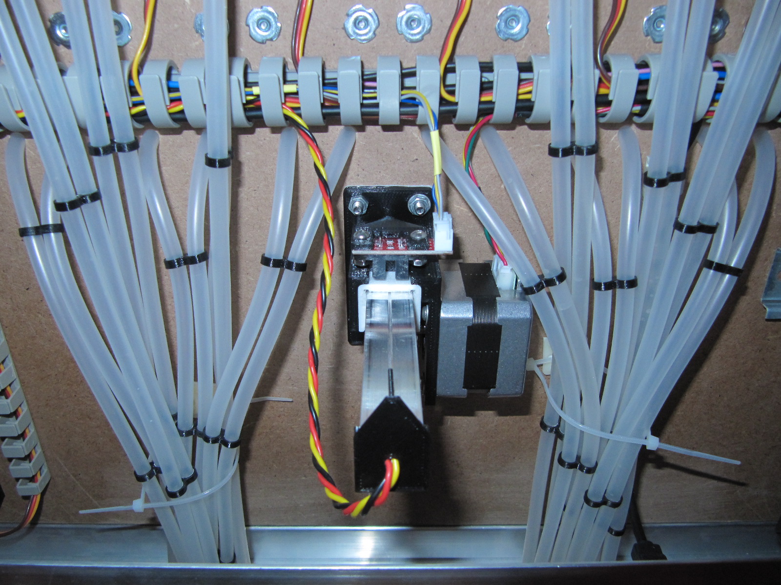
Hoses
To transport liquids and air, silicone hoses with an outer diameter of 6 mm and 4 mm inside diameter are used. In any case, care must be taken that the hoses are intended for use with food. To guide the hoses through the housing, the valves and the dosing head, it has been proven to cut off one end at an acute angle. For each ingredient, two hoses are passed through a valve. One hose directs the liquids from the bottle to the dosing head, the other hose connects the air pump and the bottle. When guiding the hoses through the housing, care must be taken that the hoses do not tangle with the arm. We just used cable ties (Fig. 9).
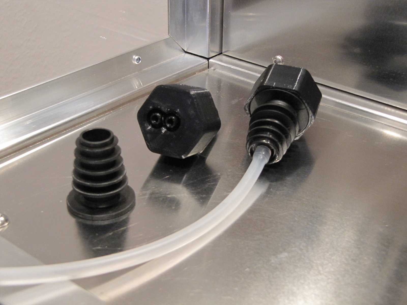
Plugs
The plugs consist of a 3D printed core and a conical seal. The seal makes it possible to connect different beverage bottles with one kind of plug. The seals can be purchased from catering supplies. When printing the cores, food grade filament should be used. On one side of the plug are the hoses leading to the valves (do not confuse air and beverage hoses!) connected. On the other side of the plug is a piece of silicone tubing connected which reaches to the bottom of the bottle.
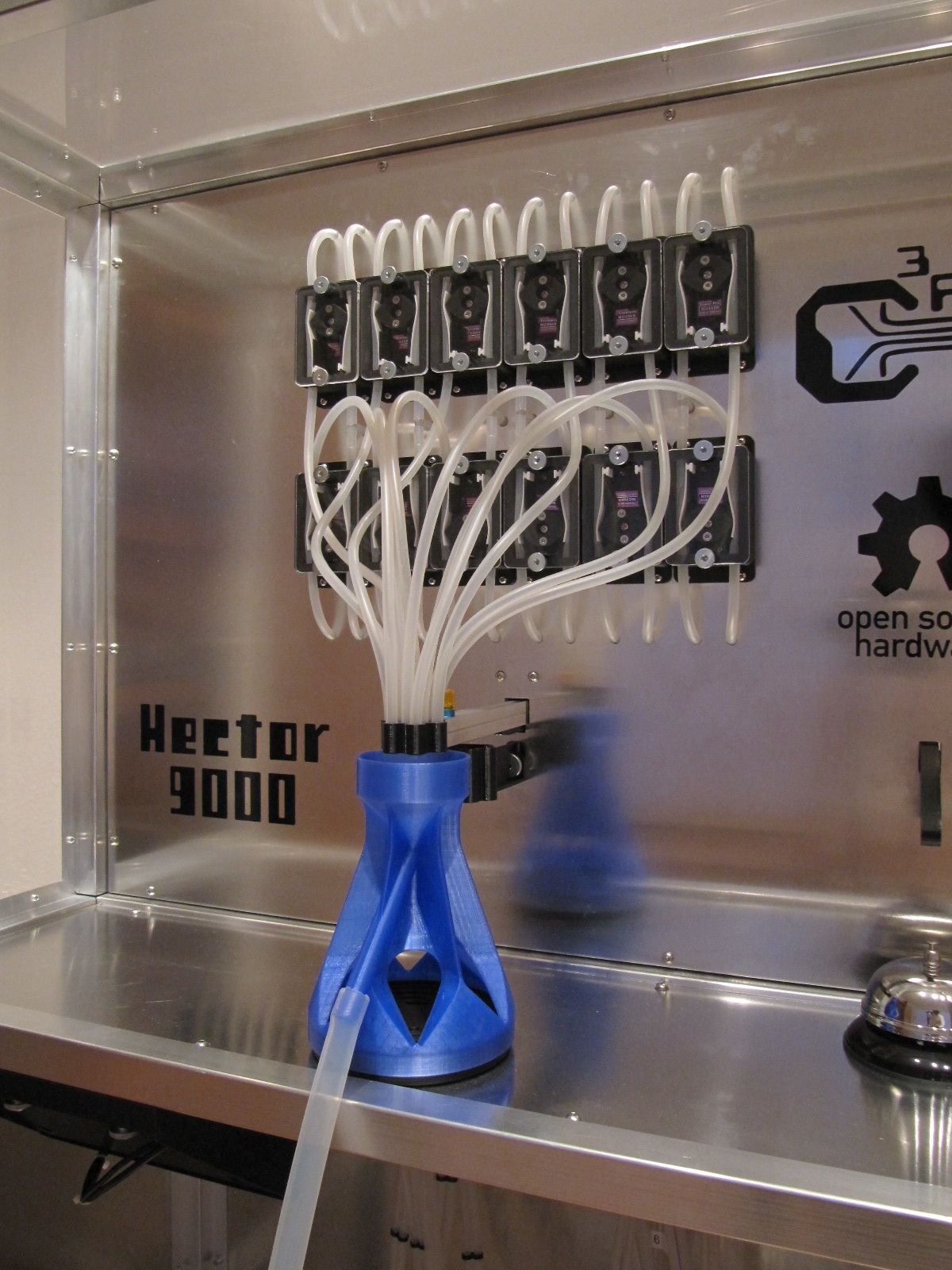
Flushing funnel
As it takes a lot of water and time to rinse the hoses, it is not much fun to stand next to Hector and empty full glasses during the wash program. We have therefore constructed a flushing funnel that transports the wastewater directly into a bucket or spout. The flushing funnel can be printed without support. The hose nozzle is designed for a silicone hose with an internal diameter of 10 mm.
Housing
The housing consists of 25 mm aluminum profiles that have been covered with aluminum sheets and PMMA sheets. The metal sheet on which the scale was attached, as well as the sheet metal which carries the valves, were additionally glued to an MDF board. Before bonding, captive nuts were placed into the MDF panels to later screw on the DIN rails and pump. The PMMA plates and most of the other plates were fixed with 4 mm blind rivets. The rear wall is fixed by M4 screws. Blind rivet nuts were used in the profiles as a counterpart to the screws. It is strongly recommended to use special sheet metal drills for machining the sheets and profiles, otherwise problems may occur when inserting the rivets. The case is not included in the bill of materials, here everyone should let their creativity run free[^1].
Display
For the selection of drinks we have opted for a 7" display with touch function via USB. The USB version is necessary because the GPIOs are used for other functions. The display is attached to a extruded profile of the housing. For transport the display can be turned into the housing (Fig. [display_half_in]). In the printed housing for the display are 3 holes for mounting it to the frame. Only two holes are needed for the attachment: the middle hole and an outer one. The display is screwed to the frame by means of blind rivet nuts and knurled screws. To turn the display, remove the outer screw and loosen the center screw.